


Flexible AC Transmission Systems
Flexible AC Transmission Systems (FACTS) is a market consisting of different application related to net quality. The most common applications are shown in figure 1 from https://www.hitachienergy.com/products-and-solutions/facts . Many FACTS manufacturers are also doing active filters and since they are not included in another report, the decision is to have them in here at least in this revision.
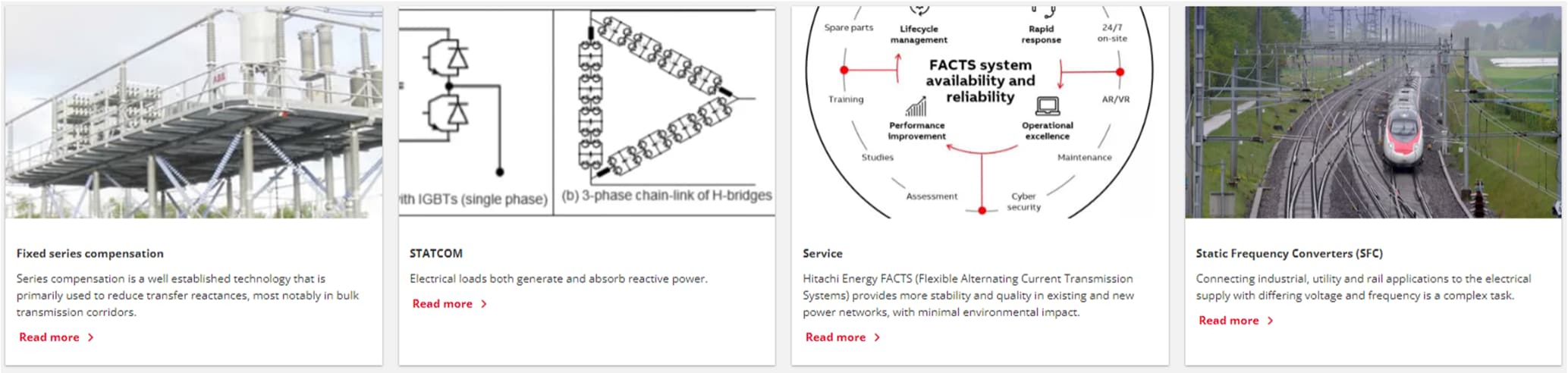
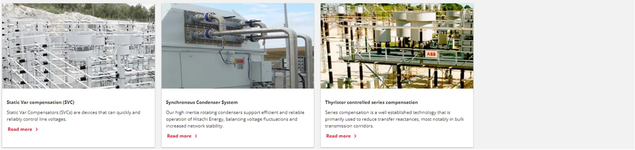
Figure 1 Typical FACTS applications.
Before we go into more technical details what the different FACTS-systems are good for, let us start with a simple example using a language that we all understand, see figure 2. If we pour beer in a glass, we get froth at the top. To maximize the amount of beer in the glass we want to remove the froth and replace it with fluid beer. In the same way do the owners of electric distribution lines only want to transmit active power (beer) and not reactive power (froth). This since you do not get paid by your customers for reactive power but is causes losses and blocks transmission capacity on the line meaning that you earn less money on your investment. To remove the froth from your line you use
for instance an SVC-system.
To compensate the reactive power, you can connect a capacitance or an inductance (normally referred to as reactor in FACTS) depending on in which direction you need to compensate. Most common is capacitance since frequent loads as electric machines are inductive. The simplest solution is fixed compensation that is used where the compen-sation need is known and relatively stable over time. One example is the series capacitor used for instance to decrease the voltage drop on long overhead lines:
When alternating current is transmitted in long lines two different kinds of voltage drops arise: active drops due to the line’s resistance, I x R, and the reactive drops resulting from the line’s reactance, I x X. With series compensation of the line, the voltage profile over the line is improved, see figure 3.

Figure 3 Compensation with series capacitor.
To improve the control of the capacitor, a thyristor assembly can be implemented, see figure 4, creating what is called a thyristor-controlled series capacitor (TCSC).
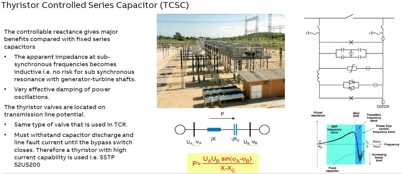
Figure 4 Compensation with thyristor-controlled series capacitor.
For cases where there are changes in the load, but these changes are predictable and slow, mechanically switched capacitors (MSC) or reactors (MSR) are used. By connecting or disconnecting capacitors or reactors with mechanical switches, we can either increase or decrease the voltage on the grid as required by the load condition, see figure 5.
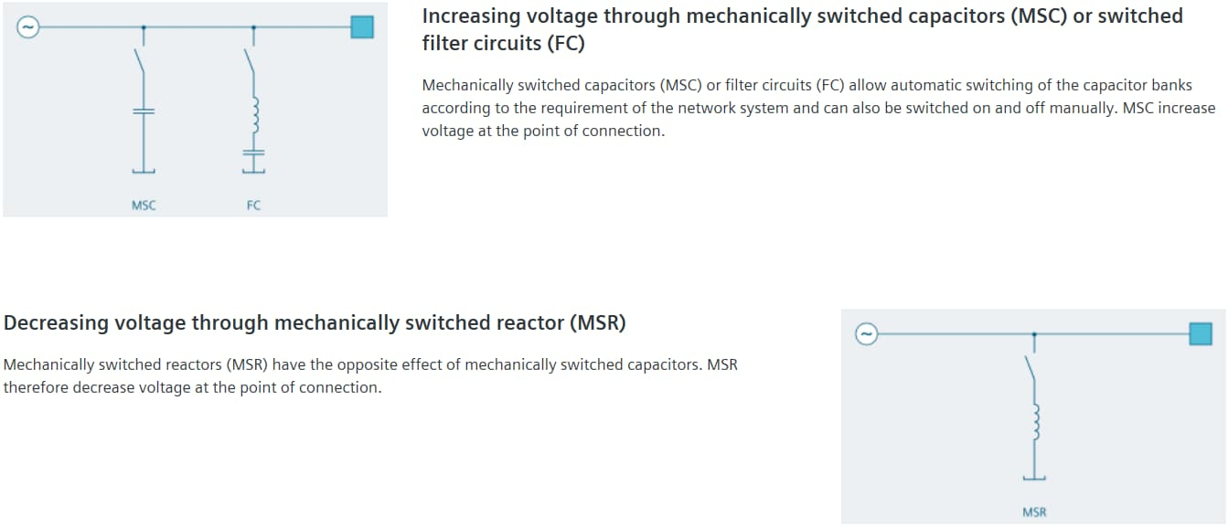
Figure 5 Mechanically switched capacitors and reactors.
In a similar manner filters and damping circuits can be switched on or off to the network, see figure 6, to improve the quality of the voltages and currents for instance by decreasing harmful frequencies.
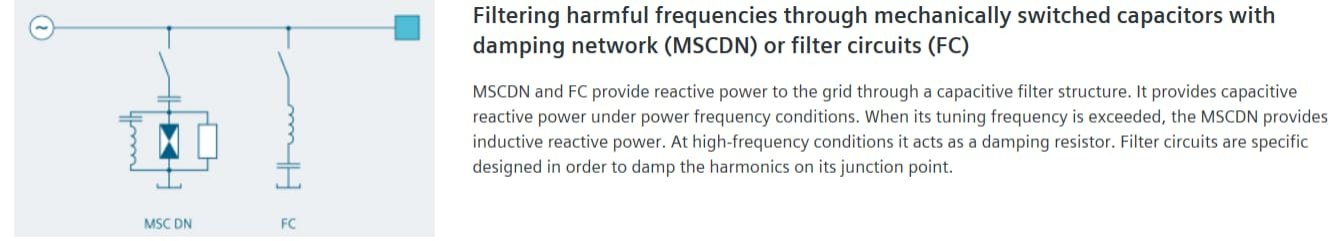
Figure 6 Additional functionality that can be built into a system with mechanically switched capacitors and reactors.
If we replace the mechanical switches in figure 5 with a thyristor, we get the classic SVC that can be either thyristor-controlled shunt connected capacitors (TSC) or inductances (TCR), see figure 7. By using thyristors, the compensation can be done much faster and more often since thyristors are wearing out much slower than mechanical breakers.
These improvements have the price in increased losses since we replace mechanical switches with basically no voltage drop with thyristor stacks. The function for the TCR and TSC and the required filters are:
The core functionality of an SVC Classic is the ability to dynamically adjust inductive reactive power with a thyristor-controlled reactor (TCR). This adjustment, performed automatically by the control system based on the dynamic grid requirements respectively the load characteristics, results in the stabilizing effect of the SVC Classic. TCRs do not generate transients, but they generate harmonic currents at firing angles above 90°. These harmonics need to be dampened by individually tuned filter circuits.
A thyristor switched capacitor (TSC) is used to inject capacitive reactive power step by step, if called for by transient phenomena during switch-on. Instead of being controlled continuously, they are switched on and off when needed.TSCs do not generate harmonic distortion in the transmission line. In industrial plants this is not a common solution.
Filters circuits enhance the capabilities of the SVC Classic. To absorb harmonics prevalent in the system or generated by the TCR, they are tuned to specific frequencies. Number and frequency characteristics are individually selected. Where necessary, high- and low-pass filters further improve effectiveness. In industrial applications usually the principle of “indirect compensation” is usually applied: filters of the SVC Classic are designed to provide a defined capacitive reactive power at base frequency– the inductance of the reactor, dynamically controlled to complement the varying reactive load, that the reactive power of all three components adds up to approximately zero.
The most common topologies for SVCs are: TCR + filter or TCR + TSC + filter. The main advantage for using a topology with TSC branch (es) is to reduce the losses (by reducing the filter size).
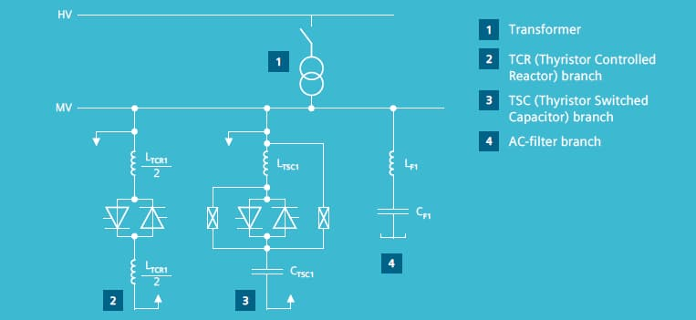
Figure 7 Thyristor controlled capacitors (TSC) and reactors (TCR).
The highest degree of compensation performance is reached by a STATCOM. Like SVC but faster, STATCOM continuously provides variable reactive power in response to voltage variations, supporting the stability of the grid.
STATCOM operates according to voltage source converter (VSC) principles, combining unique PWM (pulse width modulation) with millisecond switching. STATCOM functions with a limited need for harmonic filters, contributing to a small physical footprint. If required, switched or fixed air core reactors and capacitors can be used with the VSC as additional reactive power elements to achieve any desired range. Installing a STATCOM at one or more suitable points in a grid will increase power transfer capability by enhancing voltage stability and maintaining a smooth voltage profile under different network conditions. Its ability to perform active filtering is also very useful for improvements in power quality.
With modern converter designs as MMC the need for filter can be reduced or even removed meaning that a STATCOM solution can have a very simple circuit diagram as in figure 8.
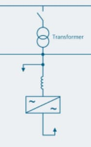
Figure 8 Simplified STATCOM circuit.
In figure 9 we find a summary once published by Siemens with features and limitations of the main FACTS solutions.
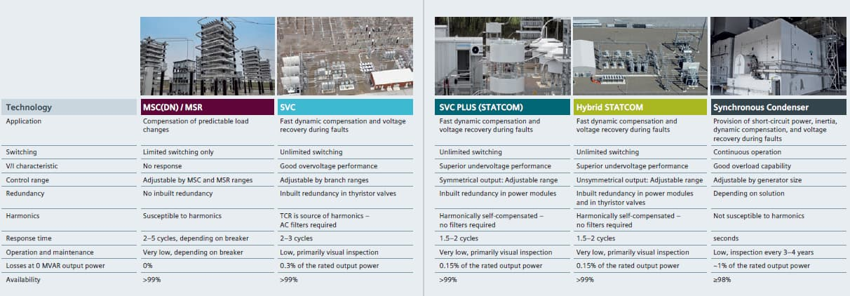
Figure 9 Comparison of FACTS solutions from Siemens.
A short explanation how an active filter is working is shown in figure 10 taken from http://www.powerqualityworld.com/2011/08/active-harmonic-filters-ahf.html . Additional information you find at some of the homepages from the manufacturers of active filters mentioned in paragraph 5, such as at https://www.india.fujielectric.com/resources/technical-guide/active-harmonic-filter .
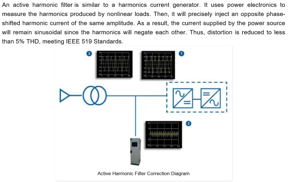
Figure 10 Short description of an active filter.
Created on:2025-02-06 10:24
넶PV:0


