


Fusion Power System — Application Guide
Fusion Power System — Application Guide
Fusion Power System
Product Overview
Nuclear fusion represents the ultimate clean energy solution for humanity's future. Fusion power systems are among the most demanding power conversion applications in existence, requiring extremely high currents (hundreds of kiloamperes), high voltages (tens of kilovolts), and exceptional precision in control. NexPower provides SCR (Silicon Controlled Rectifier) based power conversion solutions for poloidal field (PF) and central solenoid (CS) coil power supplies in fusion reactors, leveraging thyristor technology with proven reliability to meet the extreme requirements of nuclear fusion applications.
Key Advantages
✓ High current density — handles hundreds of kA with compact design
✓ High transient overload capacity — withstands extreme pulsed power demands
✓ Long service life — proven reliability under harsh operating conditions
✓ Matured technical topology — 12-pulse rectification with anti-parallel bridge configuration
✓ Bidirectional power flow — supports both rectifier and inverter modes for energy feedback
✓ Circulating current mode — eliminates dead-zone for continuous precision control
✓ Redundancy-ready architecture — meets fusion-grade reliability requirements
Technical Requirements & Challenges
Fusion Power Systems Face Extremely High Engineering and Technical Barriers:
▸ Extreme Power Requirements: Currents can reach hundreds of kiloamperes (kA) and voltages tens of kilovolts (kV). This imposes exceptionally stringent requirements on insulation, thermal management, and electromagnetic compatibility (EMC).
▸ Precision and Response Speed: Plasma control demands current regulation accuracy better than 0.1%, with dynamic response times on the order of milliseconds or even microseconds.
▸ Reliability and Redundancy: Multiple redundancy design is mandatory. No single-point failure should lead to catastrophic consequences—such as a plasma disruption or a magnet quench.
▸ Complex Coupling: Strong electromagnetic coupling exists among multiple magnet power supplies. Decoupling control algorithms are required to prevent mutual interference.
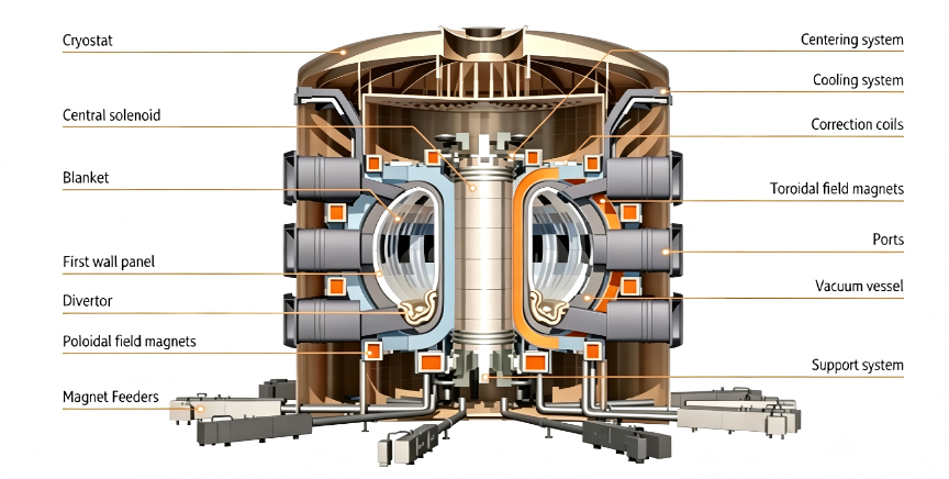
Figure: Nuclear Fusion reactor concept
Typical Application Cases
▸ Case 1: ITER (International Thermonuclear Experimental Reactor)
Its magnet power supply system is one of the world's largest pulsed power systems, with a total capacity exceeding 500 MVA. It utilizes thyristor converters coordinated with high-voltage DC circuit breakers. The system represents the most ambitious fusion energy project globally, requiring the highest standards of power conversion reliability and precision.
▸ Case 2: EAST (China)
Employs an IGBT-based chopper power supply system, achieving flexible and precise control over plasma current and position, enabling long-pulse operation (on the order of hundreds of seconds). The Experimental Advanced Superconducting Tokamak (EAST) has achieved significant breakthroughs in steady-state H-mode operation.
▸ Case 3: JT-60SA (Japan)
Similarly utilizes high-power thyristor converters equipped with fast shutdown protection capability. This upgraded tokamak project aims to support ITER by exploring advanced plasma configurations and contributing to the global fusion research effort.
SCR-Based Solution Architecture
NexPower's SCR-based solution for PF/CS coil power supplies employs a proven 12-pulse rectifier topology designed specifically for the extreme demands of fusion applications.
Core Architecture (Single Converter Unit, CU)
• Input Transformer: The unit is powered by two phase-shifting transformers (e.g., configured in Δ/Y and Δ/Δ), generating a 30° phase shift to eliminate specific harmonic orders and form a 12-pulse rectification configuration.
• Power Bridges: The system comprises four 6-pulse thyristor bridges (two bridges per transformer secondary), providing robust and scalable power conversion capability.
• Anti-Parallel Structure: The four bridges are divided into two groups (Group A and Group B) connected in an anti-parallel (back-to-back) configuration. One group handles positive voltage output, while the other manages negative voltage output. Energy feedback to the grid is achieved by switching the firing angle.
• Key Parameters: Typical rated current for a single CU is 27.5 kA or 55 kA (achieved via parallel units), with an operating voltage of ±1.35 kV.
Figure: Core architecture of single converter unit (CU)

Operating Modes
▸ Rectifier Mode (Power Output): One bridge group operates with a firing angle α < 90°, providing either positive or negative DC voltage to energize the coil.
▸ Inverter Mode (Power Absorption): When rapid field weakening is required, the firing angle is adjusted to α > 90°, allowing the energy stored in the coil to be fed back to the grid.
▸ Circulating Current Mode: Near the zero-crossing point of the current, both bridge groups operate simultaneously (one rectifying, one inverting) to maintain a circulating current. This eliminates the current dead zone and ensures continuous control precision.
12-Pulse Rectifier Topology — Poloidal Magnetic Field
The poloidal magnetic field power supply adopts a 12-pulse rectifier topology formed by two 6-pulse rectifiers in parallel. Each 6-pulse rectifier uses 12 SCRs (Silicon Controlled Rectifiers) in parallel configuration, with the proven 5STP52U5200 thyristor as the core switching device.
SCR-based solution key characteristics:
✓ High current density — optimized for kA-level operation
✓ High transient overload capacity and long operational life
✓ Proven high reliability matching Nuclear Fusion requirements
✓ Matured technical topology with extensive field validation
Figure: 12-pulse rectifier (2×6 pulse) topology for Poloidal Field


Technical Specifications (Summary)
───────────────────────────────────────────────────────
|
Parameter |
Specification |
|
Application |
Poloidal Field (PF) / Central Solenoid (CS) Coil Power Supply |
|
Topology |
12-Pulse Thyristor Rectifier (2×6 Pulse, Anti-Parallel) |
|
Device |
SCR 5STP52U5200 (12 devices in parallel per arm) |
|
Rated Current |
27.5 kA / 55 kA (per CU, parallel configurable) |
|
Operating Voltage |
±1.35 kV DC |
|
Configuration |
Δ/Y + Δ/Δ Phase-Shifting Transformer Input |
|
Operating Modes |
Rectifier / Inverter / Circulating Current |
|
Current Precision |
< 0.1% regulation accuracy |
|
Response Time |
Millisecond to microsecond level |
Recommended Products
5200V Phase Control Thyristors — 5STP Series — Purpose-built for fusion-grade pulsed power applications. Features high current density, superior surge capability, and proven long-term reliability in ITER-class systems.
© NexPower Electronics Co., Ltd. | www.nexpower.com


